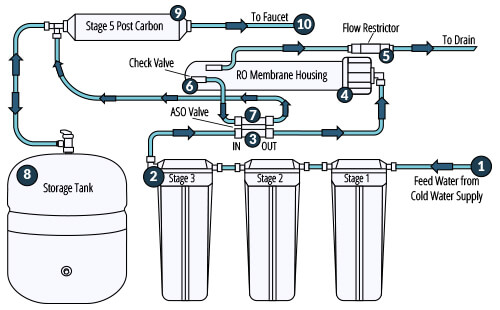
About Reverse Osmosis Water Filtration

Reverse Osmosis (RO) is a water purification process that uses pressure to force water molecules through a semipermeable membrane to remove impurities and contaminants. The 0.0001 micron* pores (holes) in the reverse osmosis membrane prevent the larger molecules of dissolved impurities from passing through with the smaller water molecules. The result is clean, high quality drinking water.
reverse-osmosis-diagram
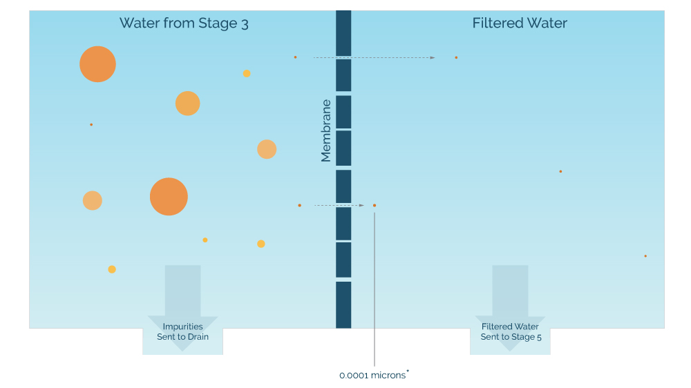
*A micron is a unit of length, for example most bacterial cells range from 0.2 to 1 micron in width. Filters with "nominal" pore size have an average pore size of the micron size listed, which means that some of the pores are smaller or larger than the listed micron size. Please note that this image is not to scale.

What can reverse osmosis remove from drinking water?

According to the CDC, reverse osmosis will remove protozoa, bacteria, viruses and common chemical contaminants from drinking water:
  • Reverse Osmosis Systems will remove common chemical contaminants (metal ions, aqueous salts), including sodium, chloride, copper, chromium, and lead; may reduce arsenic, fluoride, radium, sulfate, calcium, magnesium, potassium, nitrate, and phosphorous.
  • Reverse Osmosis Systems have a very high effectiveness in removing protozoa (for example, Cryptosporidium, Giardia);
  • Reverse Osmosis Systems have a very high effectiveness in removing bacteria (for example, Campylobacter, Salmonella, Shigella, E. coli);
  • Reverse Osmosis Systems have a very high effectiveness in removing viruses (for example, Enteric, Hepatitis A, Norovirus, Rotavirus);

How Does a Reverse Osmosis System Work?

Anatomy of a 5-Stage Reverse Osmosis System

The drinking water filtration process in a reverse osmosis system is completed in stages: pre-filtration, reverse osmosis, storage, drainage, and post-filtration.

The easiest way to understand how the filtration process in a reverse osmosis system works is to understand the basic functions of the individual parts of the system. Although some RO systems may have a different number of pre or post filters, in general, all RO systems consist of the same core components.
reverse osmosis system water flow diagram
  1. Feed Water The incoming water from the cold water supply. The water enters the reverse osmosis system at the full pressure (psi) of the cold water supply.
  2. Pre-Filters (Stages 1-3) The source water pressure forces the water through the three pre-filters to remove sediment, chlorine, taste and odor before the water reaches the reverse osmosis membrane (Stage 4).
  3. ASO Valve In/Out (High-Pressure Side) The inside of the Automatic Shut-off Valve (ASO) contains a rubber piston sandwiched between two rubber diaphragms. The diaphragm on this high-pressure side of the ASO Valve responds to the pressure (psi) of the incoming water from the pre-filters to allow the water to proceed into the reverse osmosis membrane housing.
  4. Reverse Osmosis Membrane (Stage 4) The water pressure forces the water molecules through the reverse osmosis membrane to filter out impurities and contaminants.
  5. Flow Restrictor The flow restrictor slows the flow of water to the drain. This creates back pressure on the membrane to maintain the separation of the water into wastewater and filtered water. While the RO system is filtering water, there will be water flowing through the flow restrictor and to the drain.
  6. Check Valve The filtered water from the membrane flows out of the check valve and into the bottom side of the ASO valve. The check valve is a one-way valve, creating a barrier between the membrane and the ASO valve. With the check valve, the ASO valve can correctly react to the back pressure from the storage tank.
  7. ASO Valve (Low-Pressure Side) The diaphragm on this side of the ASO valve responds to the back pressure (psi) from the storage tank. Once the storage tank is full, the back pressure from the tank will be 60% of the feed water psi. At this pressure, the diaphragm will push the rubber piston inside the valve against the opposite diaphragm to create a seal, this stops the flow of water from the pre-filters and turns off the system.
  8. RO Storage Tank Filtered water flows from the ASO valve and directly into the tank through the tee-connection on the stage-5 filter. The filtered water is stored in a protective bladder inside the metal storage tank until the system faucet is turned on.
  9. Post-Carbon Filter (Stage 5) When the system faucet is turned on, the change in pressure between the storage tank and the faucet will pull the filtered water from the tank through the stage-5 post carbon filter before it reaches the faucet.
  10. RO System Faucet The faucet will dispense the filtered water stored in the tank. If the amount of water dispensed from the faucet reduces the tank back pressure on the ASO valve below 60% of the incoming water pressure, the ASO valve will turn on the RO system to refill the tank with filtered water.